The Hummingbird Cam is a motion-triggered camera, featuring an ESP32-CAM development board and a passive infrared sensor.
Inspiration
Since May 2020, I have observed the hummingbirds that come to drink from the feeders set up around my house. I was able to take some decent pictures of them with a DSLR:
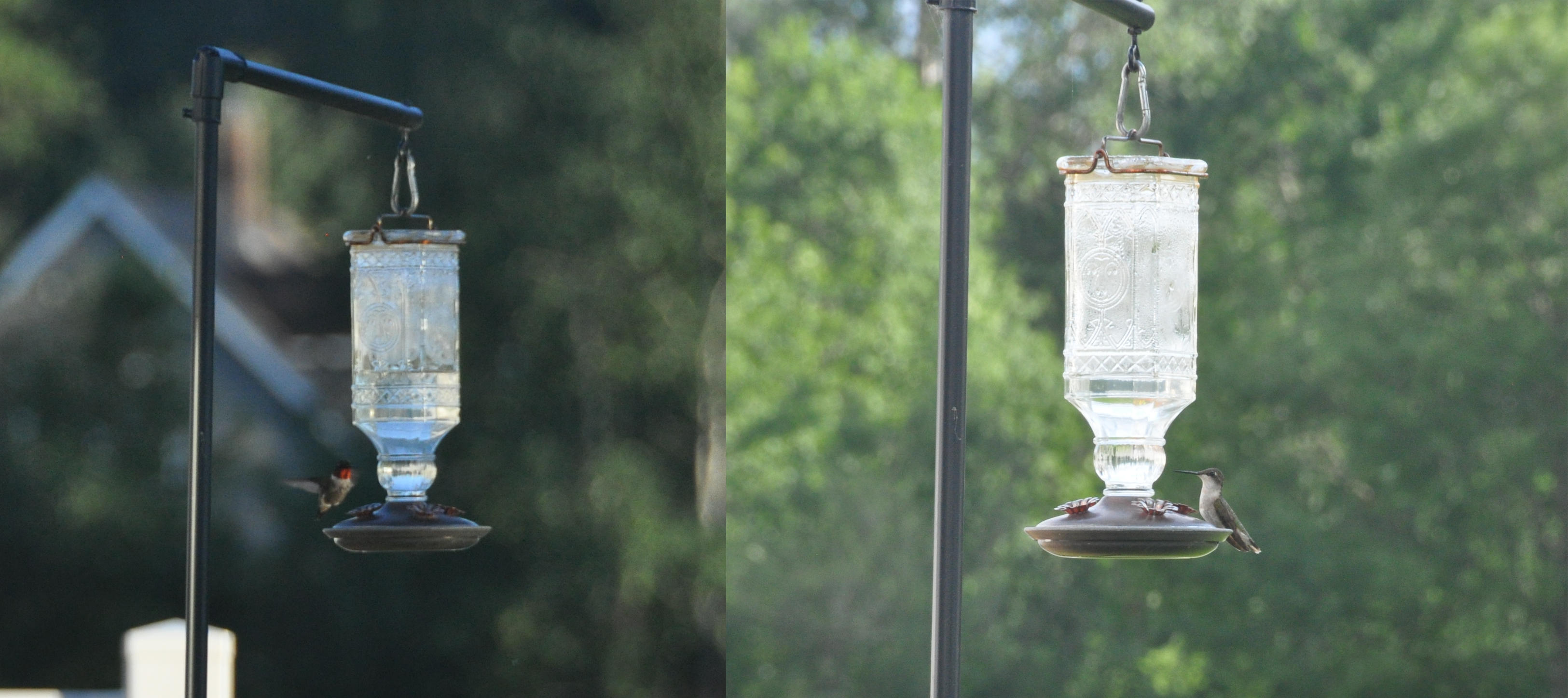
Photos taken with a Nikon D90 DSLR camera.
While I am able to take high-quality pictures of the hummingbirds with a normal camera, I have to wait for them to appear and manually take a photo each time. I would also sometimes startle the hummingbirds if I got too close, causing them to fly away. This is when I came up with the idea of using a motion-triggered camera. A motion-triggered camera would be able to take pictures of the hummingbirds up close without disturbing them. Products like this exist already for taking pictures of animals (trail cams), but that would take the fun out of building one.
Components
After doing some research online, I found components that would help me achieve this goal. The following section describes the devices and parts I used to build the Hummingbird Camera.
ESP32-CAM
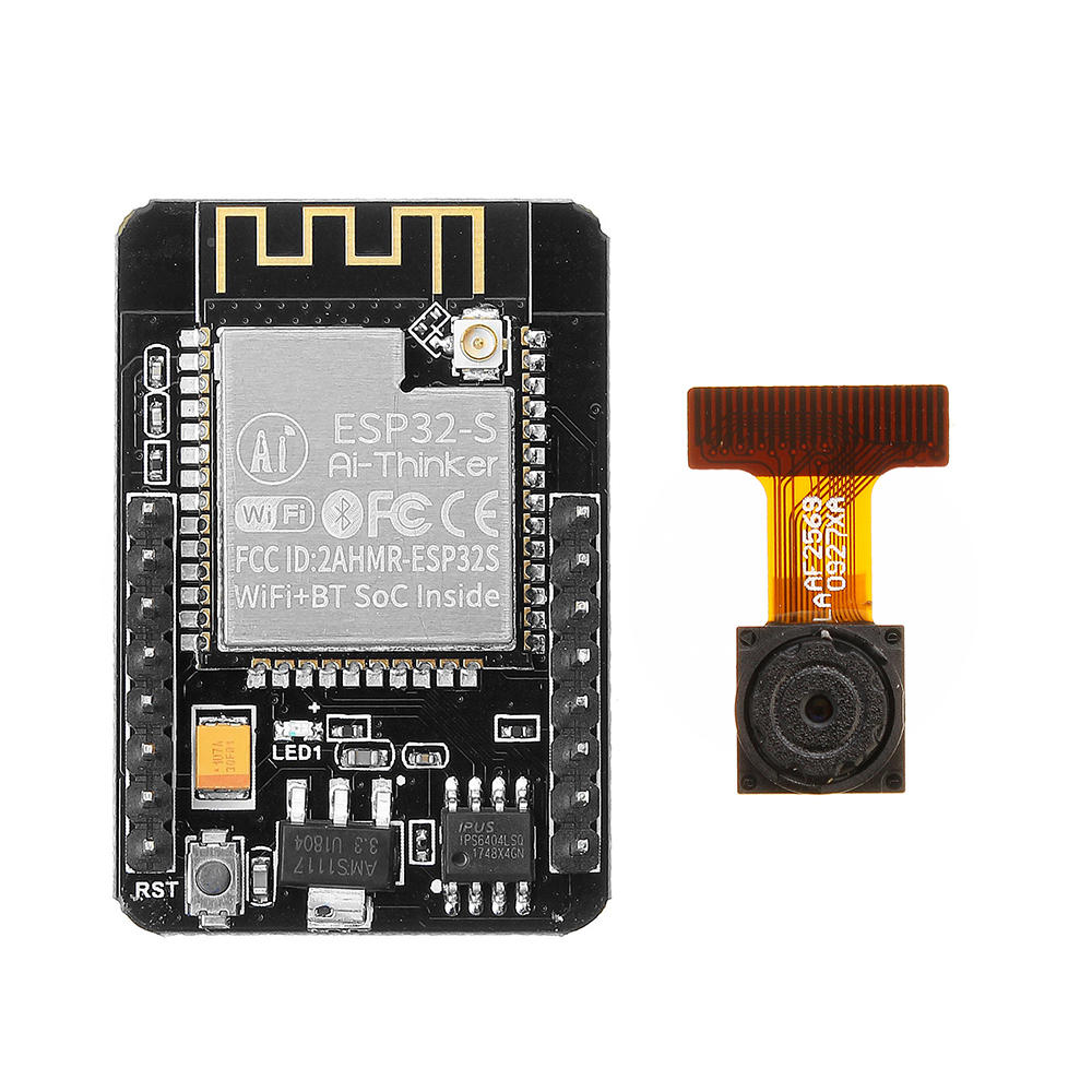
The ESP32-CAM is a development board created specifically for use with a camera module. It uses the ESP32-S microcontroller developed by Espressif Systems. The microcontroller itself operates on 3.3V, but the development board has a built-in voltage regulator to convert a 5V input to the required 3.3V. Some of its specifications are listed below:
- Dual-core 32-bit microprocessor, with adjustable clock speed from 80MHz to 240MHz
- 520kB RAM + 4MB PSRAM
- ULP co-processor
- WiFi and Bluetooth connectivity
- Built-in SD card slot
- ZIF connector for camera module
Detailed specifications for the ESP32-S microcontroller can be found in its datasheet.
The ESP32-CAM comes with an OV2640 camera module, a 2MP camera that supports a maximum resolution of 1632x1232. The picture settings can be modified in software, which can change the brightness, exposure, saturation, etc.
The ESP32-CAM can enter a deep-sleep state, where it only draws 20μA-150μA depending on the usage of the ULP coprocessor. The ESP32-CAM can wake up from deep sleep using an external wakeup as described on Espressif’s website.
HC-SR501 Passive Infrared Sensor
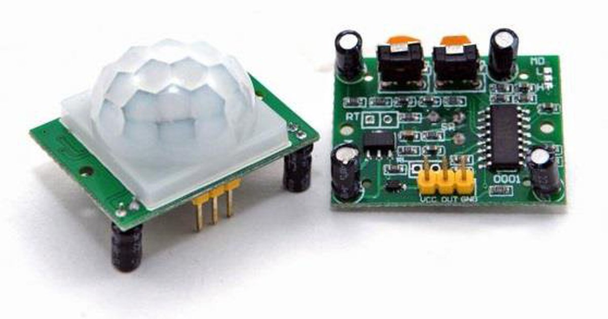
The HC-SR501 passive infrared (PIR) sensor is used to detect motion. It accepts an input voltage range from 5V to 20V and outputs a 3.3V signal when it detects motion. The time the signal is high and the detection range can be adjusted using the potentiometers on the board. The module also has two modes: single-trigger mode, where the output pulses for the set duration, or continuous mode, where the output stays high as long as it detects movement.
18650 Lithium-Ion Battery
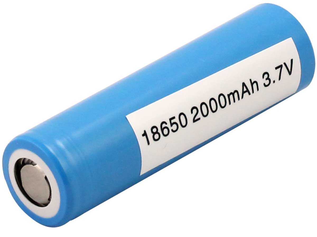
I chose to use an 18650 battery from an old Raspberry Pi handheld project I worked on back in 2017. The one I used has a 2000mAh capacity.
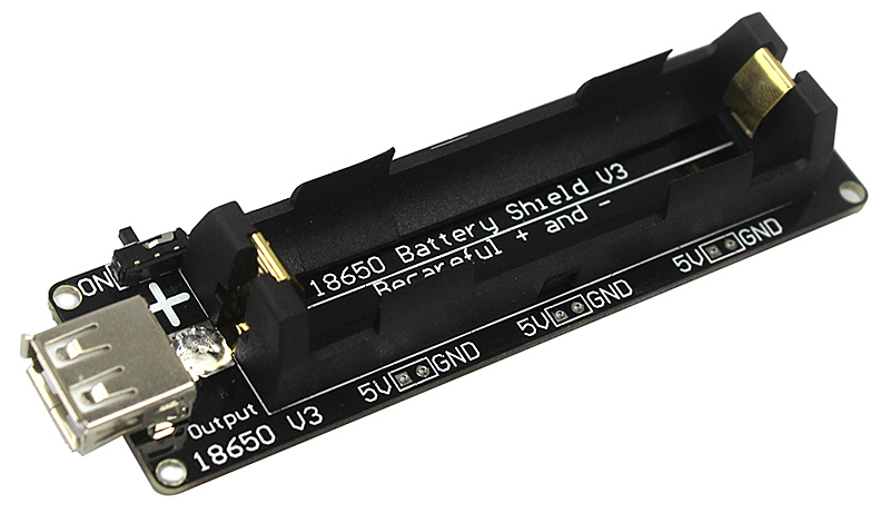
Additionally, I used a modified 18650 Raspberry Pi shield from the same project, which essentially manages the power usage of the battery. It allows the battery to recharge from a 5V input and it steps up the 3.7V from the battery to a 5V output.
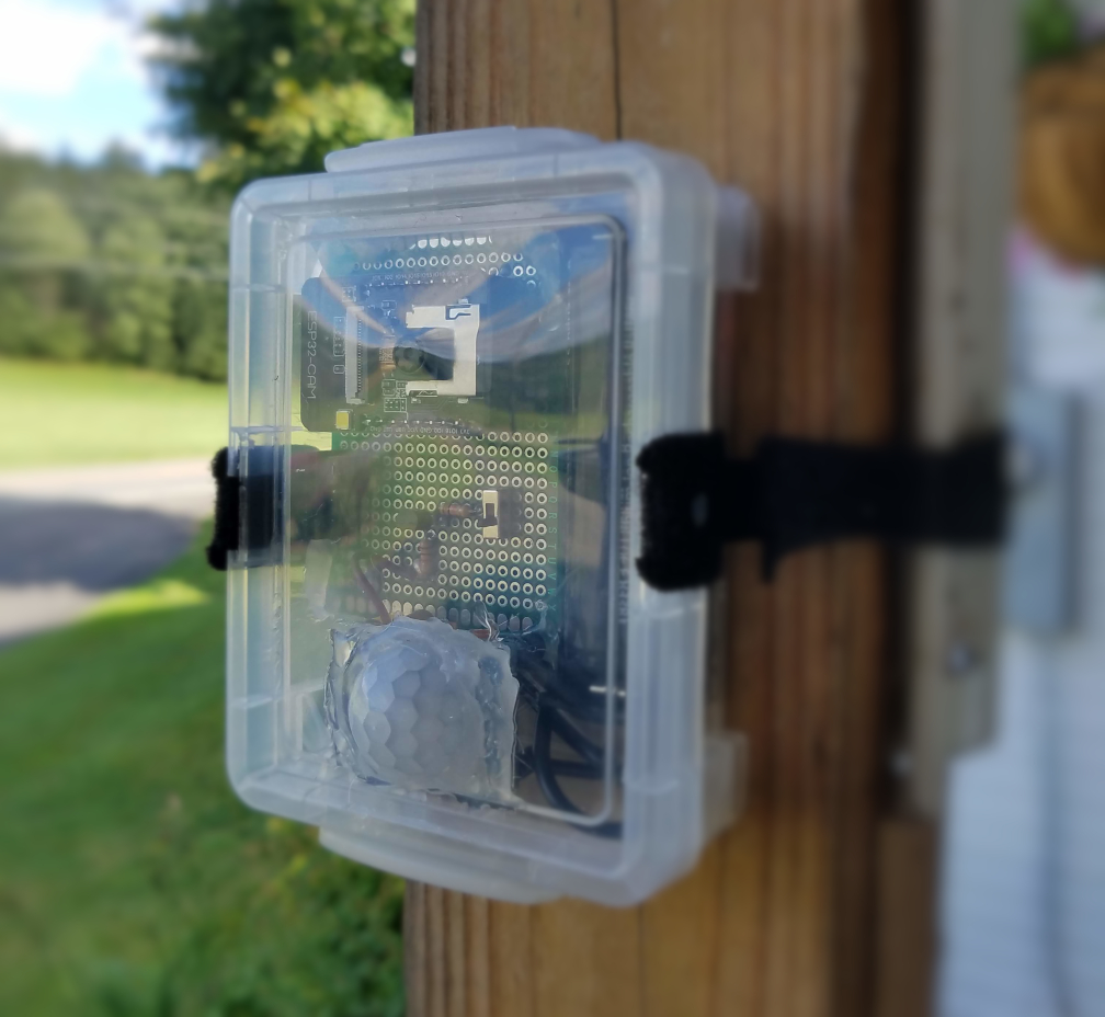
Crayon Box

Believe it or not, the case is actually a crayon box. I used this as the project’s enclosure because it’s small, readily available, and extremely low-cost: they’re only $1 each at the local supermarket. It’s also clear enough to take decent pictures through it while still offering some degree of protection from the elements.
I tested the water resistance of the box by placing paper inside, closing it, and putting it in the shower for a few minutes. It keeps out most of the water on its own, but some drops managed to slip in. This is mitigated by either sealing or covering the edges with each use. Covering each edge from front to back with plastic wrap and tape keeps all droplets out. The seal can also be made tighter by placing a thick tape around the edge, where the lid touches the case. The case can’t withstand being submerged for very long, so no underwater pictures.
Various Other Parts
To hold everything together, I used a solder board, female and male header pins, wires, and hot glue. A male USB cable was tucked inside and can be extended outside of the case to recharge the battery. A small switch was added to turn the device on and off. A Dremel was used to make a hole in the lid for the sensor to fit through.
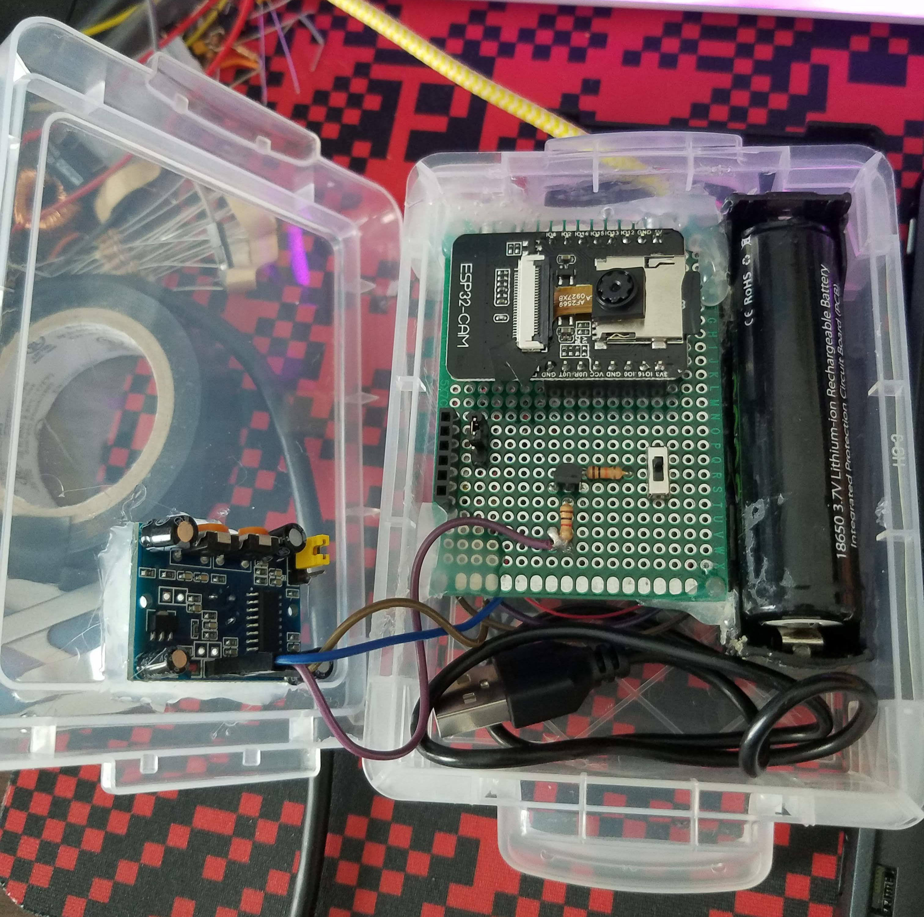
I initially used zip-ties to hold the camera in place, but I cut two slots on either side of the case later on for reusable Velcro straps.
There is a header on the left side of the solder board for connecting a serial programmer, and a jumper for grounding IO-0 to put the ESP32-S into download mode. Programming the ESP32-CAM is tedious, as the jumper has to be moved back and forth when testing new code.
Note: I used a BJT circuit to pull a pin on the ESP32-CAM to ground whenever the PIR module triggered, but I later learned that I didn’t need it; the software does support wakeup from a HIGH signal. I may still be able to use the circuit for a future purpose that I’ll discuss later.
Programming
The Arduino IDE is used to program the ESP32-CAM, with an additional extension provided by Espressif. The code is written in C++. An external serial programmer is required to program the board, as it doesn’t have a USB port. The code I used for this can be found on my Github profile.
Results
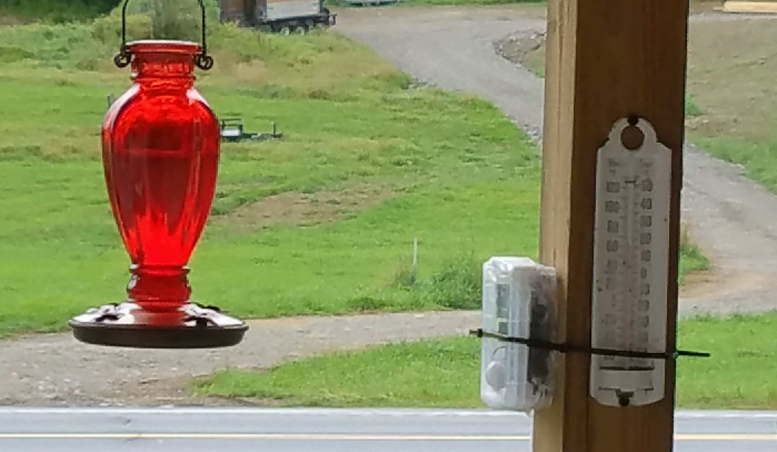
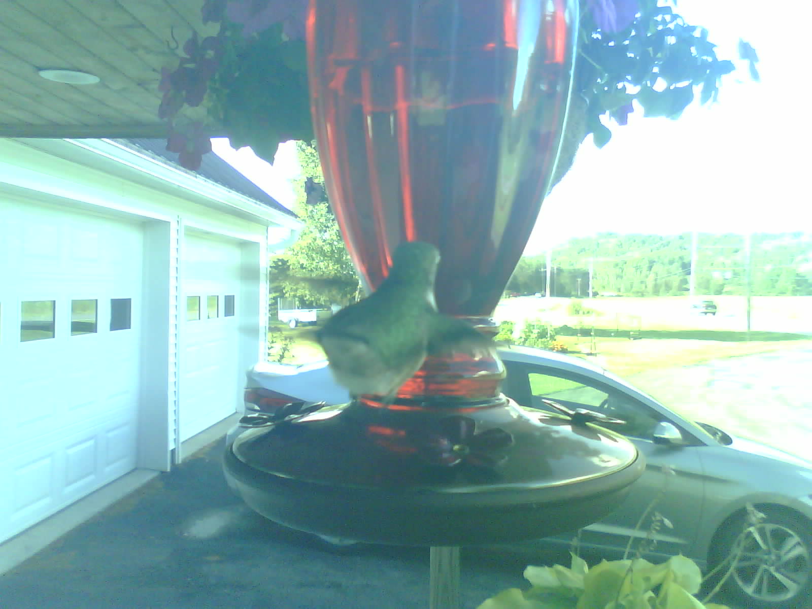
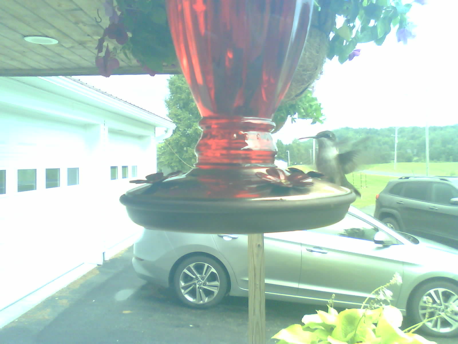
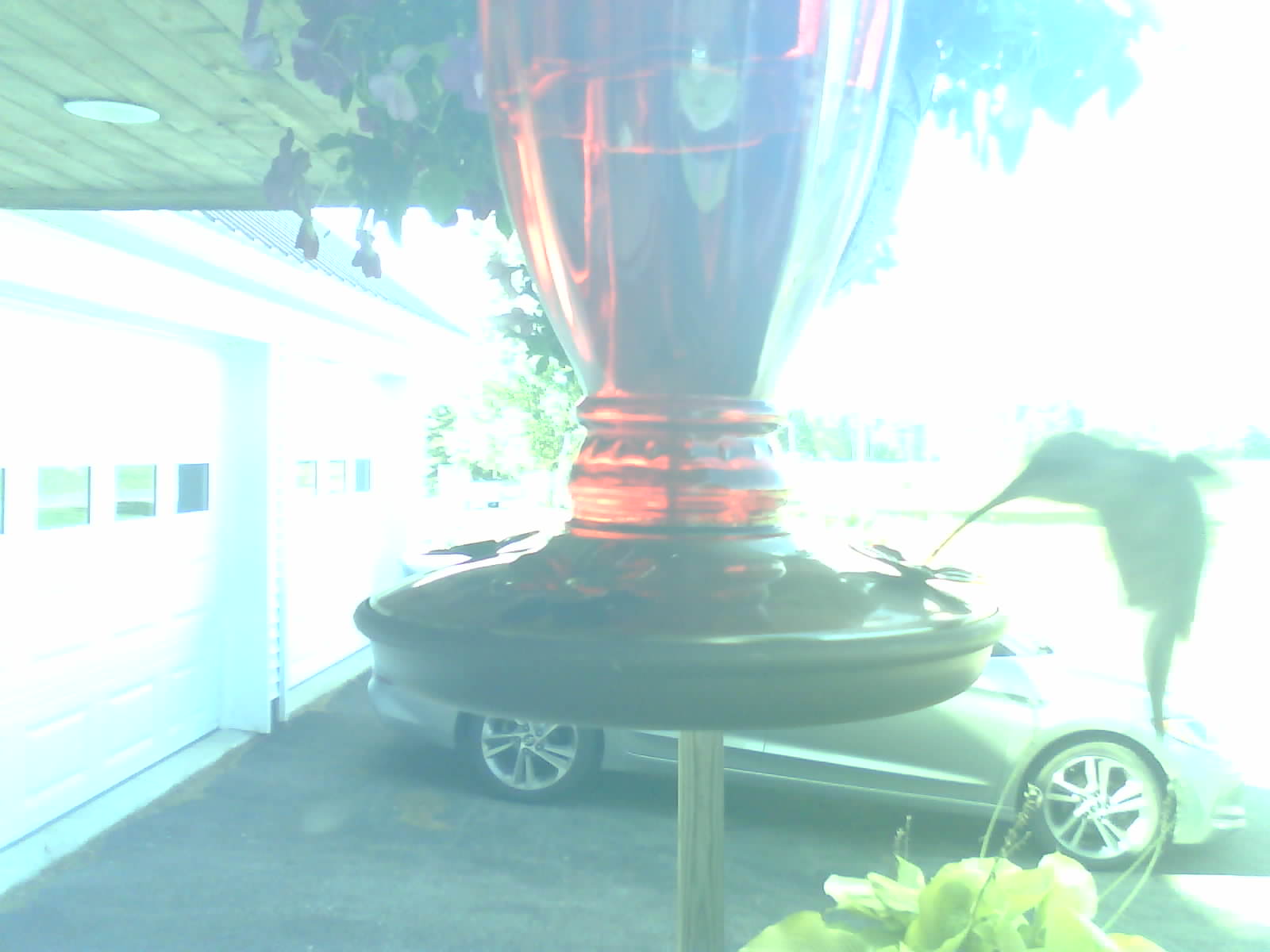
The Hummingbird Cam functioned as intended when set up next to a hummingbird feeder. It sometimes triggers from the wind blowing the feeder and nearby plants around, but in most cases it captures the intended subjects. Below are some of the best photos taken so far:
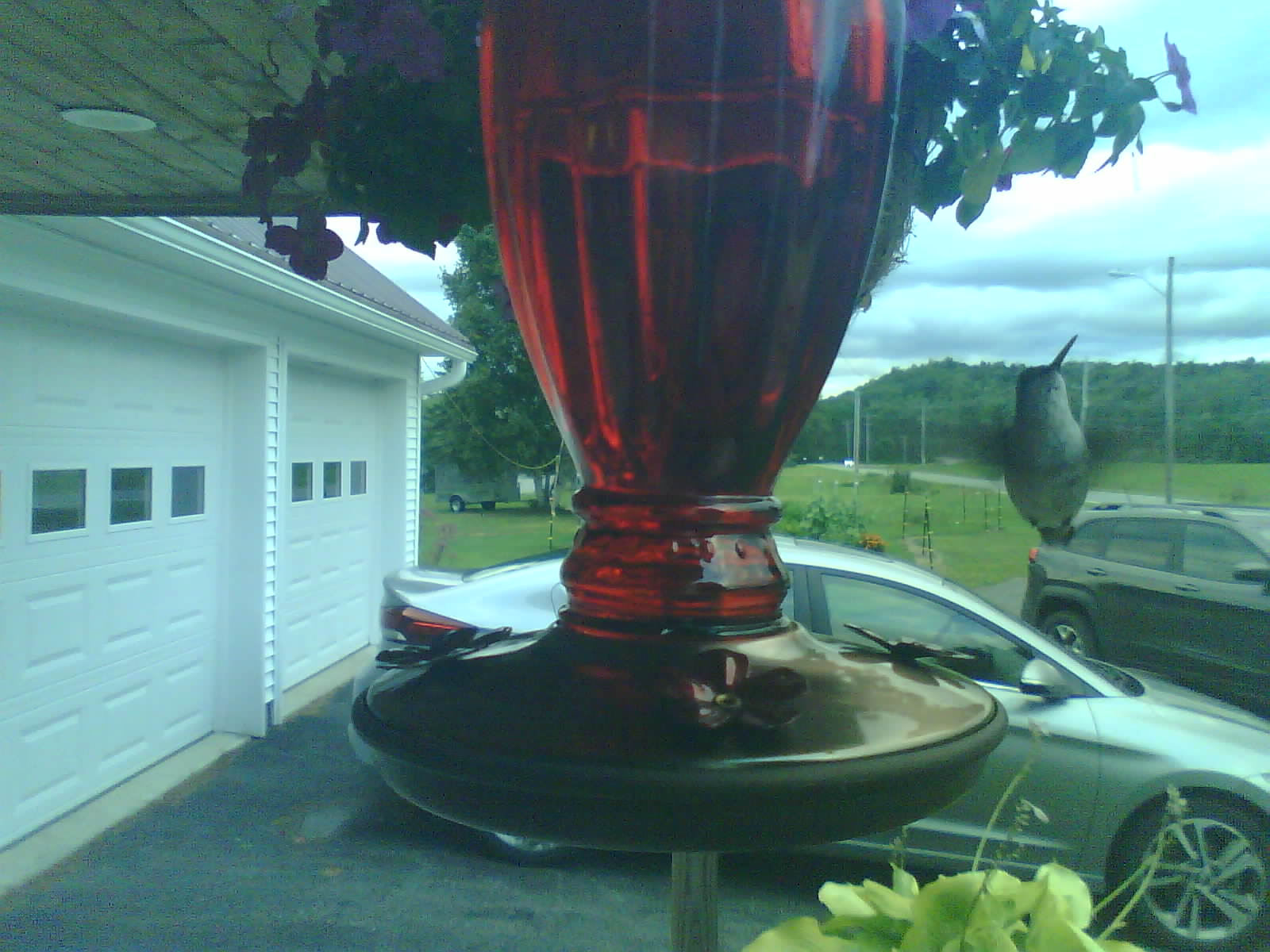
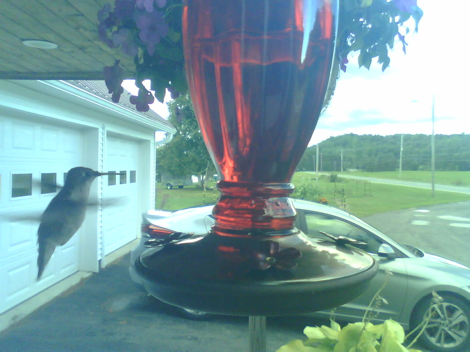
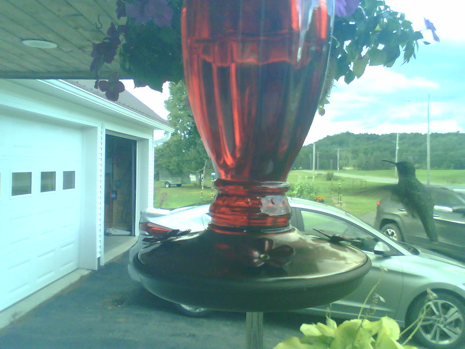
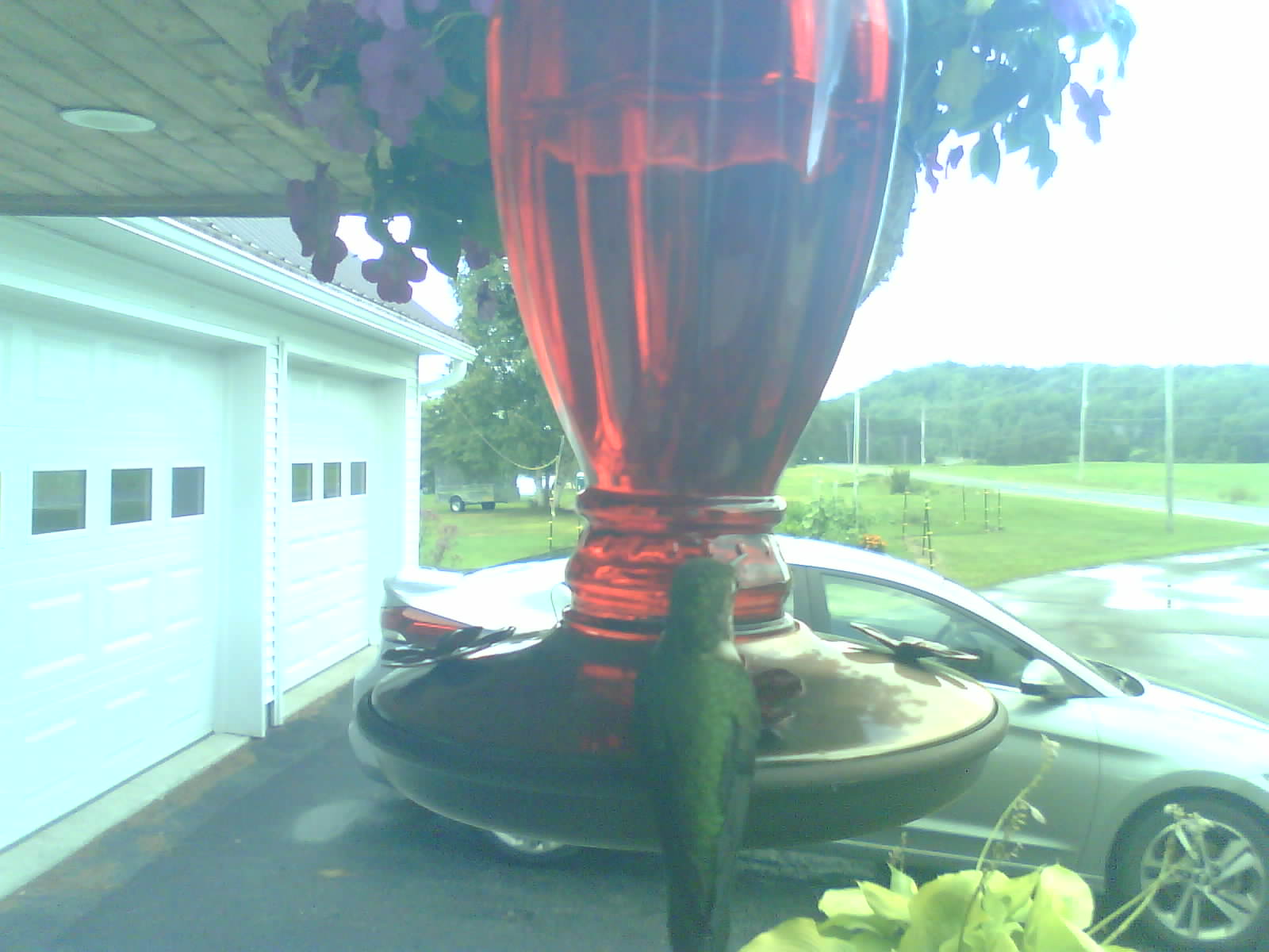
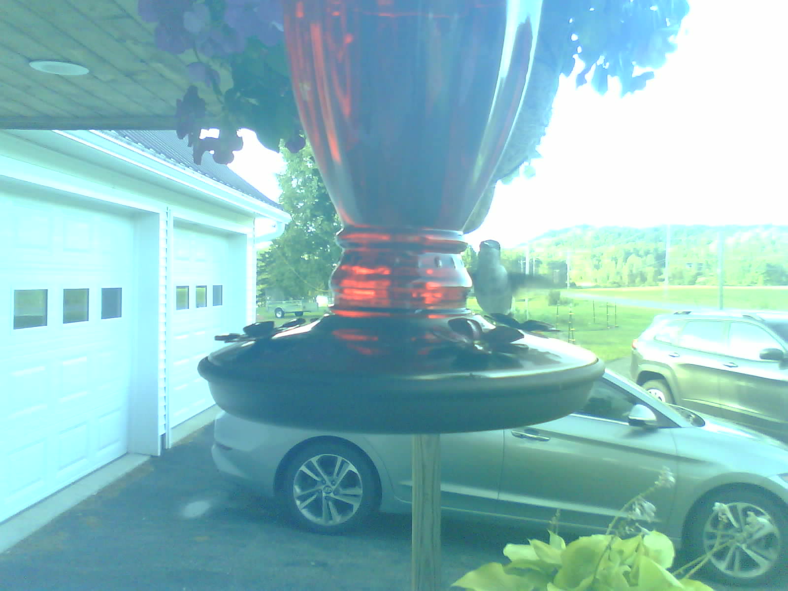
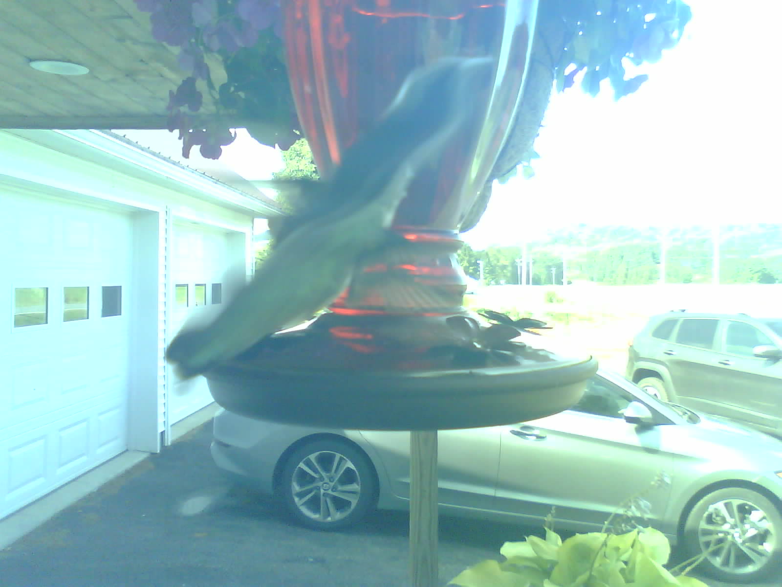
There were also a couple of interesting moments captured by the camera, but they are less clear:
The Hummingbird Cam works reasonably well, but there are still a few issues to work out. The brightness and saturation in some of the photos are far too high. This seems to have the worst impact during the day, when the sun shines brightest on that side of the house. It takes better photos during the afternoon and evening. These parameters can be adjusted to an extent in software.
The case used to protect the electronics also adds a slight blue tint to the images. This can easily be corrected on a computer, but it is possible to do this on the ESP32-CAM right after taking a picture.
Future Work
I’ve looked into adding more features to the Hummingbird Cam, as it is pretty simple in its current state. Some of the features I’d like to add are listed below:
1. Power usage monitoring
2. Photos with the proper timestamp
3. A hardware user interface
4. A Bluetooth interface that can be accessed through an Android app
5. Temperature sensors, for inside and outside the enclosure
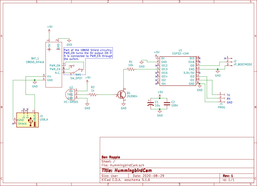
6. A better charging port for the 18650 shieldImplementing these features using only the ESP32-CAM to control all the peripherals may present an issue. Below is a schematic of the ESP32-CAM development board:
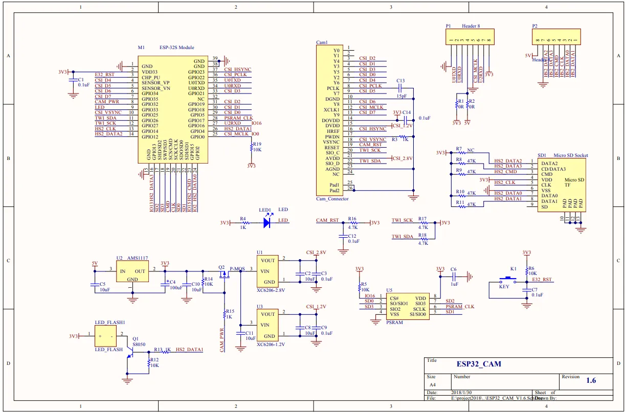
The top right-hand corner of the schematics shows the two 8-pin headers on either side of the module. Every pin is either designated for power, ground, download mode, or a signal line for the SD card and camera. If I used these pins for anything else, it would potentially interfere with using the SD card. The only pins that won’t interfere with the camera and SD card are U0TXD and U0RXD: the pins used for serial communication. Since I want to use both the SD card and the camera, I want to avoid connecting anything else to those pins, except HS2_DATA3 as the ext0 RTC wakeup pin.
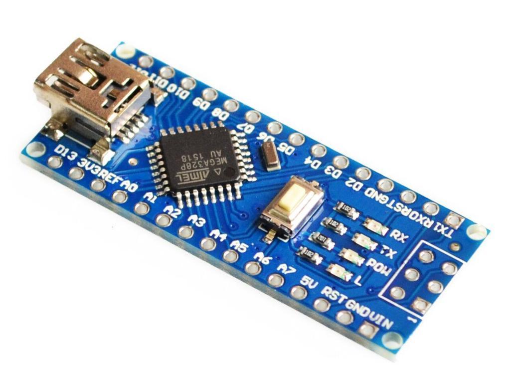
I’ve contemplated adding an Arduino Nano (with some bidirectional level shifters) inside the case as a companion device. The Arduino would be able to exchange information with the ESP32-CAM using serial communication on U0TXD and U0RXD, and would consume less power than leaving WiFi or Bluetooth on.
The Arduino could also have an extra benefit: It can eliminate the need for an external programmer, since it can be programmed as one. If the BJT pull-down circuit is connected to an Arduino output at the base, and the collector output is changed to pull down IO-0 on the ESP32-CAM, the Arduino could ground the download pin on the ESP32-CAM automatically before programming.
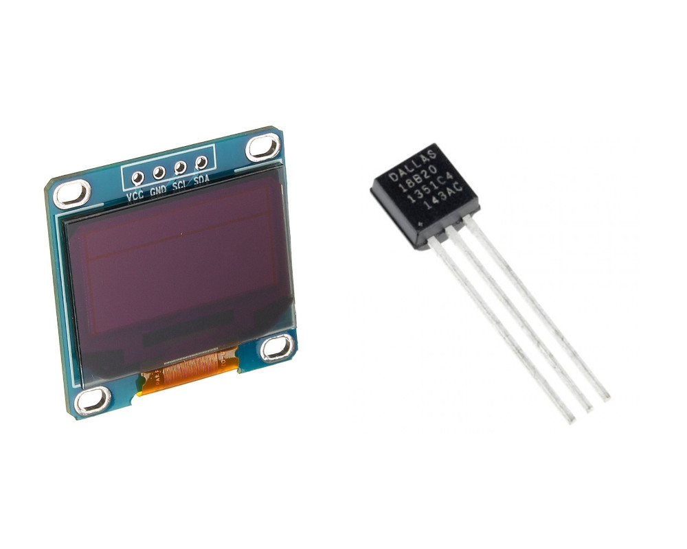
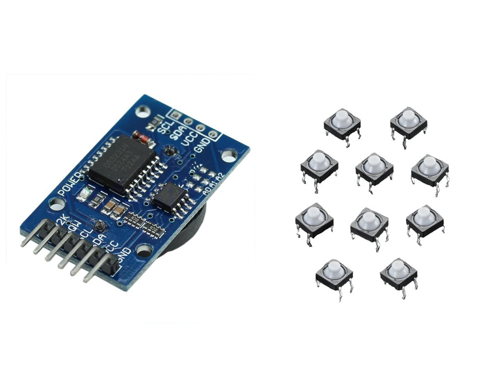
When not being used to program the ESP32-CAM, the Arduino can be switched to a different mode to support peripherals like a small i2c display, an i2c real-time clock (RTC), some one-wire temperature sensors, and several buttons. The Arduino can read the voltage level of the battery and the output of a Hall Effect sensor using its ADC inputs. The Arduino could then communicate with the ESP32-CAM over the same serial pins it uses to program it. When not in use, the Arduino can enter deep sleep mode, similarly to the ESP32-CAM.
As of now, I think I am limited to a single GPIO pin for wakeup, since ext1 wakeup mode uses pins that aren’t exposed on this board. To get around this, I can have the Arduino send a code over serial as it triggers the wakeup and have the ESP32-CAM enter a different mode as it receives it. This would only need a few milliseconds to process, and would be sufficient to know the difference between a motion trigger wakeup and an Arduino wakeup.
The WiFi capability of the ESP32-CAM could be used to update its own internal RTC at periodic intervals or after receiving a command; however, its RTC is not very accurate and has no battery backup. It would be better in my case to use a more accurate RTC module with a small battery backup to store time information, and only update it as needed.
These proposed additions require testing to see if it will work. I already have all the parts I need to get this working, so a future post will describe how this goes.
Device Schematics
The schematics are pretty simple for this version:
Conclusion
This post has described the purpose, programming, construction, and deployment of the Hummingbird Cam. It succeeded in capturing many interesting photos of hummingbirds. I hope to improve the device so I can use it in different situations and to photograph other kinds of animals. I will make a post describing the features I add when they’re finished. Thanks for reading!